
Chapter 23: Electric Circuits
Equations Introduced and Used for this Topic:
Parallel Resistors: Series Resistors:
Vs = V1 = V2 = V3 = … Is = I1 = I2 = I3 = …
Is = I1 + I2 + I3 + … Vs = V1 + V2 + V3 + …
[latex]\dfrac{1}{R_{T}} =\dfrac{1}{R_{1}} +\dfrac{1}{R_{2}} +\dfrac{1}{R_{3}}[/latex] … RT = R1 + R2 + R3 + …
Kirchoff’s Circuit Laws:
∑ Vsource = ∑ Vdrops (Conservation of Energy)
∑ I into node = ∑ I out of node (Conservation of Charge)
Where:
I is the Electric Current, measured in Amperes or Amps (A)
V is the Voltage, measured in Volts (V) R is the Resistance, measured in Ohms (Ω)
23.1 Ohm’s Law (Single Circuits)
Equations Introduced:
Ohm’s Law relates Voltage, Current and Resistance given by the equation of
V = IR
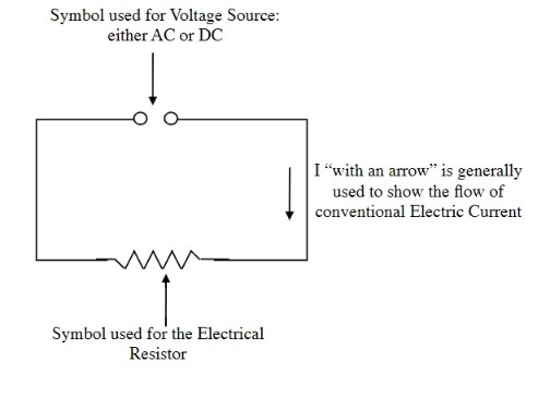
In this last Chapter for this course, we analyze basic electric circuits using Ohm’s Law and later Kirchoff’s Laws in series, parallel and combined resistor arrangements. While there are a number of circuit symbols are used in circuit diagrams:

We use the symbol of jagged lines for electrical resistance.
We use two open circles to represent the Source Voltage.

Combined in a simple circuit these symbols look like:
The following examples use the circuit diagram to solve for Ohm’s Law questions:
EXAMPLE 23.1.1
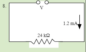
Find the missing variable for each of the following circuits:
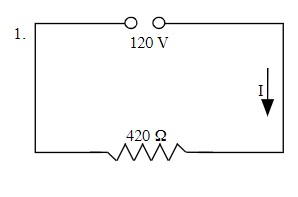
V = IR
120 V = I (420 Ω)
I = 120 V ÷ 420 Ω or 0.29 A
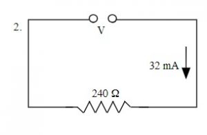 V = IR
V = (32 x 10-3 A)(240 Ω)
V = 7.7 V
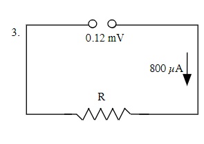 V = IR
0.12 x 10⁻³ V = (800 x 10-6 A)(R)
R = 0.12 x 10⁻³ V ÷ 800 x 10-6 A
R = 0.15 Ω
QUESTIONS 23.1 Ohm’s Law
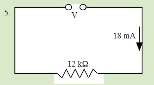
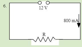
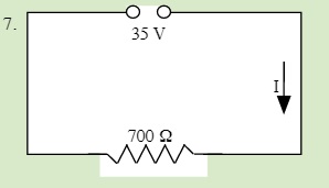
Solve for the unknown in each of the following single circuits
23.2 Series Resistors 3
Equations Introduced:
RT = R1 + R2 + R3 +
The equation we use to analyze both series and parallel resistors in combination can be found by using the original law developed for measuring the resistivity of resistors.
In general, this law follows the form: [latex]\text{R = ρ}\dfrac{L}{A}[/latex]
Where:
R is the Resistance of the resistor measured in Ohms (Ω)
ρ is the resistivity of the material, which is a measure of how well the material conducts electricity
L is the length of the conductor measured in Metres (m)
A is the cross sectional area of the conductor measured in square metres (m2)
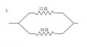
Resistors in series are simply resistors that are connected to each other and will look similar to:
![]()
From the equation for calculating the resistivity of a resistor as shown above,
[latex]\text{R = ρ}\dfrac{L}{A}[/latex]
the resultant of adding resistors one after another in a series effectively changes the length which can be easily envisioned by just considering adding identical resistors to each other which in simplest terms is just changing the length. We only need to add these resistances up.
This strategy works for all different kinds of resistors added to each other. Simply add up the total resistance of each resistor, which yields:
RT = R1 + R2 + R3 +
EXAMPLE 23.2.1
Find the total resistance of the following Resistors connected in Series:
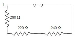
RT = R1 + R2 + R3 +
RT = 240 Ω + 220 Ω + 280 Ω
RT = 740 Ω
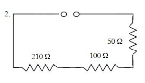
RT = R1 + R2 + R3 + …
RT = 50 Ω + 100 Ω + 210 Ω
RT = 360 Ω
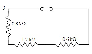
RT = R1 + R2 + R3 +
RT = 0.6 kΩ + 1.2 kΩ + 0.8 kΩ
RT = 2.6 kΩ
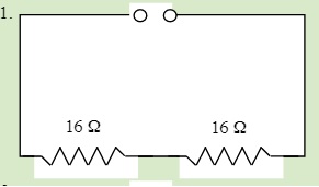
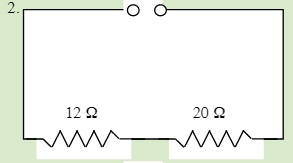
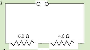
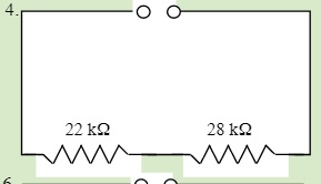
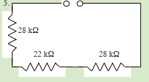
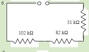
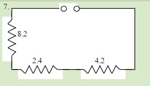
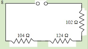
QUESTIONS 23.2 Series Resistors
Find the total resistance of each of the following circuits:
23.3 Parallel Resistors 4
Equations Introduced:
[latex]\dfrac{1}{R_{T}} =\dfrac{1}{R_{1}} +\dfrac{1}{R_{2}} +\dfrac{1}{R_{3}}[/latex]
When resistors are combined in a parallel arrangement (side by side) the total resistance can once again be inferred by the original equation that is used to calculate the resistance of a resistor. From the equation for calculating the resistivity of a resistor as shown below:
[latex]\text{R = ρ}\dfrac{L}{A}[/latex]
One way of looking at resistors that are combined in parallel is that the cross sectional area of the resistor is increased. When put together these resistors combine to allow more electricity to flow in a circuit. This means that we can simply add up the increased areas to get some measure of how the total resistance changes.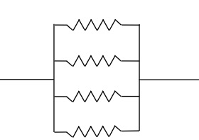
From the original equation, you will notice that the effect of changing the cross sectional area of the resistor is in the denominator or is the reciprocal variable in calculating the resistance for resistors combined in this fashion. This means that when combining resistors connected in parallel we are changing the cross sectional area in the denominator by adding new resistors that increase this cross sectional value.
Combining resistors in parallel means that we add the reciprocals of all the resistors connected in parallel to arrive at the total resistance of the new circuit.
This equation looks like:
[latex]\dfrac{1}{R_{T}} =\dfrac{1}{R_{1}} +\dfrac{1}{R_{2}} +\dfrac{1}{R_{3}}[/latex]
The following examples analyze the total resistance of resistors in parallel.
EXAMPLE 23.3.1
Find the total resistance of the following Resistors connected in Parallel:
[latex]\dfrac{1}{R_{T}} =\dfrac{1}{R_{1}} +\dfrac{1}{R_{2}} +\dfrac{1}{R_{3}}[/latex]
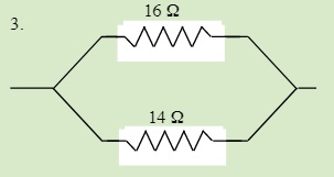
[latex]\dfrac{1}{R_{T}} =\dfrac{1}{20 Ω} +\dfrac{1}{30 Ω}[/latex]
RT = 12 Ω
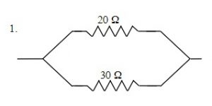
[latex]\dfrac{1}{R_{T}} =\dfrac{1}{R_{1}} +\dfrac{1}{R_{2}} +\dfrac{1}{R_{3}}[/latex]
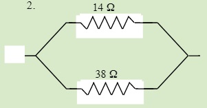
[latex]\dfrac{1}{R_{T}} =\dfrac{1}{145 Ω} +\dfrac{1}{185 Ω}[/latex]
RT = 81.3 Ω
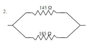
[latex]\dfrac{1}{R_{T}} =\dfrac{1}{R_{1}} +\dfrac{1}{R_{2}} +\dfrac{1}{R_{3}}[/latex]
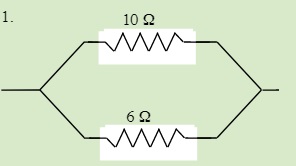
[latex]\dfrac{1}{R_{T}} =\dfrac{1}{12 Ω} +\dfrac{1}{16 Ω}[/latex]
RT = 4.1 Ω
[latex]\dfrac{1}{R_{T}} =\dfrac{1}{R_{1}} +\dfrac{1}{R_{2}} +\dfrac{1}{R_{3}}[/latex]
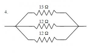
[latex]\dfrac{1}{R_{T}} =\dfrac{1}{15 Ω} +\dfrac{1}{12 Ω}[/latex]
RT = 4.3 Ω
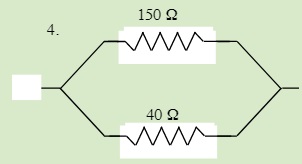
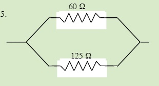
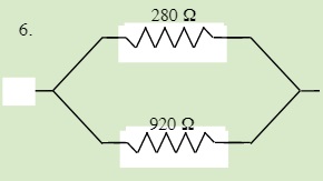
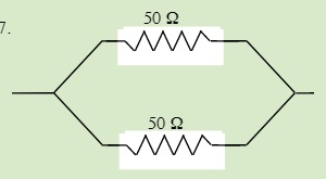
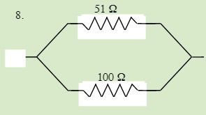
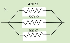
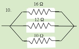
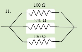
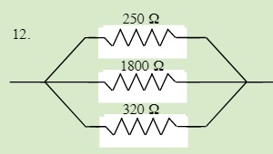
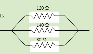
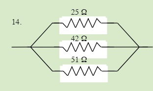
QUESTIONS 23.3 Parallel Resistors
Find the total resistance of each of the following circuits:
23.4 Series & Parallel Resistors: Total Resistance
Equations Used:
[latex]\dfrac{1}{R_{T}} =\dfrac{1}{R_{1}} +\dfrac{1}{R_{2}} +\dfrac{1}{R_{3}}[/latex] RT = R1 + R2 + R3 +
When we try to find the total resistance of combined series and parallel circuits we generally reduce the circuits from the simplest combination to the most complex.
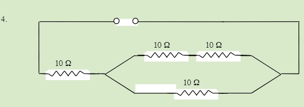
For instance when we consider the following circuit arrangement:
You can see that we have a mix of a parallel resistors connected in series to a single resistor. The simplest way to reduce this is to reduce the parallel resistors to find a single resistor of equal value. After we have reduced the parallel branch we then just add the two resistor values together as if joined in series. This looks like:
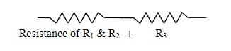
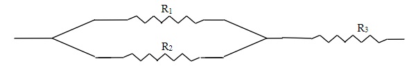
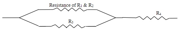
If we complicate this arrangement by adding another resistor in series to R1, we get the following:
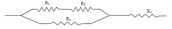
First we reduce the top branch of R1 & R2 to a single Resistor; we then continue to reduce as we did in the combination shown above.
EXAMPLE 23.4.1
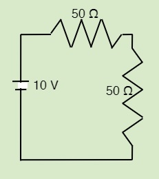
Find the total resistance of the following Resistors connected in Series and Parallel
To find the total resistance of this circuit you must identify and solve each part of the circuit. In this circuit, you have a parallel branch, which is combined in series.
First the parallel branch:
[latex]\dfrac{1}{R_{T}} =\dfrac{1}{R_{1}} +\dfrac{1}{R_{2}} +\dfrac{1}{R_{3}}[/latex]
[latex]\dfrac{1}{R_{T}} =\dfrac{1}{50 Ω} +\dfrac{1}{50 Ω}[/latex]
RT = 25 Ω
Second the series
RT = R1 + R2 + R3 +
RT = 25 Ω + 50 Ω + 50 Ω
RT = 125 Ω
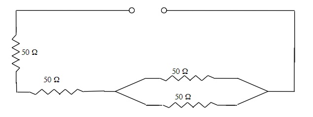
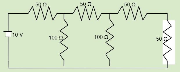
EXAMPLE 23.4.2
Find the total resistance of the following Resistors connected in Series and Parallel.
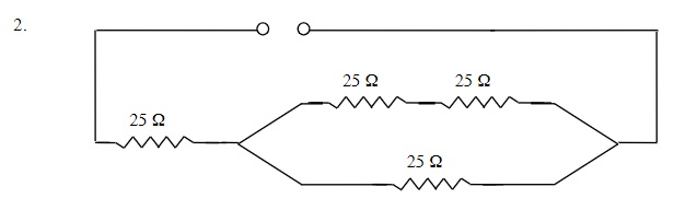
To find the total resistance of this circuit you have three distinct parts: a series branch in a parallel branch which is finally combined in series.
First, the series:
RT = R1 + R2 + R3 +
RT = 25 Ω + 25 Ω
RT = 50 Ω
Second, the parallel branch:
[latex]\dfrac{1}{R_{T}} =\dfrac{1}{R_{1}} +\dfrac{1}{R_{2}} +\dfrac{1}{R_{3}}[/latex]
[latex]\dfrac{1}{R_{T}} =\dfrac{1}{50 Ω} +\dfrac{1}{25 Ω}[/latex]
RT = 16.7 Ω
Finally the total circuit
RT = R1 + R2 + R3 +
RT = 25 Ω + 16.7 Ω
RT = 41.7 Ω (≈ 42 Ω)
QUESTIONS 23.4 Series & Parallel Resistors
Find the total resistance of the following circuits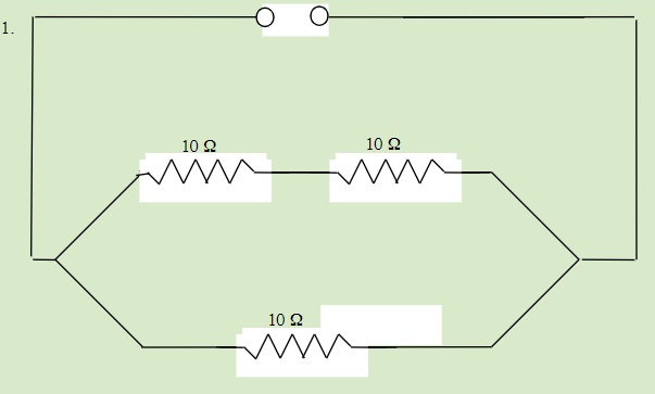
23.5 Solving Series & Parallel Resistor Circuits 5
Kirchoff’s Circuit Laws are extensions of the concept of conservation of energy and the law of conservation of charge applied to circuits.
From the Conservation of Charge: the current entering any junction (node) of a circuit is equal to the current leaving that junction (node).
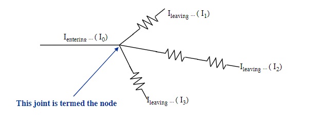
Ientering = Ileaving
Applying Kirchoff’s Law for the above circuit: I0 = I1 + I2 + I3
From the Conservation of Energy: the sum of all the voltages around the loop is equal to zero or for a simple circuit: the voltage at the source is equal to the voltage drops along the circuit.
Vsource = ∑ Vdrops
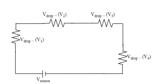
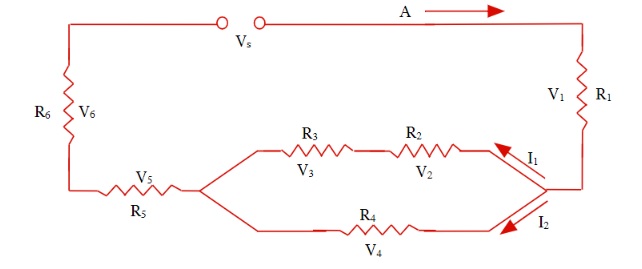
Applying Kirchoff’s Law for this circuit: Vs = V1 + V2 + V3 + V4
The final part of this section includes adding Kirchoff’s Laws to Ohm’s Law and applying the techniques to reduce combined series and parallel circuits. Ultimately you will be looking to see if you can use any one of these to reduce some part of the circuit.
Some of the rules that you must remember are:
In a series circuit:
• The electric current remains constant throughout the circuit.
• The sum of all the voltage drops (or losses) will add to the original source voltage.
In a parallel circuit:
• The voltage drop on any parallel branch will be identical to another.
• The electric current will split up in each of the branches. The sum of the electric current in each branch will equal the electric current going into the branches.
You will Use Ohm’s Law:
• Whenever you know two of the three variables in any part of the circuit, you can apply Ohm’s Law to that part.
Solving circuits can sometimes resemble a puzzle:
• Somewhere in the circuit is generally one small thing that you are able to solve. Solving this part will then lead to another part that you can solve. The challenge is that you will need to search for the one thing that you can solve in the circuit, which then allows you to solve another part.
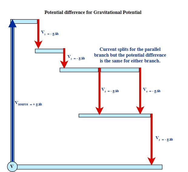
Vs = V1 + V2 + (V3 or V4) + V5
g∆hsource = g∆h1 + g∆h2 + g∆h(3 or 4) + g∆h5
One common way to visualize the voltage drops, as related to the source voltage, is to imagine a water pump leading to a series of water falls (Gravitational Potential Analogy). The source pump (source voltage) lifts the water up through a certain height, meaning that the potential difference allows the water to then fall through a series of water falls. Note: for the parallel branch of V3 & V4, both branches fall through the exact same parallel difference and are equal. What is unique about the parallel branch is that the water splits into two currents, which then recombine back into a single current after the water has passed through both branches.
EXAMPLE 23.5.1
Find the missing variable for each of the following circuits:
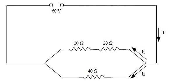
First, find the total resistance of the circuit.
The top branch is in series, so:
First, the series Third, apply Ohm’s Law
RT = R1 + R2 + R3 + V = IR
RT = 20 Ω + 20 Ω 60 V = I(20 Ω)
RT = 40 Ω I = 60 V ÷ 20Ω or 3.0 A
Second, the parallel branch. Since the resistance over the top and bottom branches are identical, the current splits evenly.
[latex]\dfrac{1}{R_{T}} =\dfrac{1}{R_{1}} +\dfrac{1}{R_{2}} +\dfrac{1}{R_{3}}[/latex]
[latex]\dfrac{1}{R_{T}} =\dfrac{1}{40 Ω} +\dfrac{1}{40 Ω}[/latex] Therefore: I1 = I2 = 1.5 A
Currents I1 & I2 can also be found by using
RT = 20 Ω Ohm’s law for each branch.
EXAMPLE 23.5.2
Find the missing variable for each of the following circuits:
This is solved in several steps.
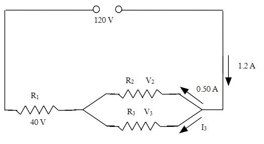
R1 V = I R1 R2 V = I R2
40 V = (1.2 A) R1 80 V = (0.50 A) R2
R1 = 40 V ÷ 1.2 A R2 = 80 V ÷ 0.50 A
R1 = 33.3 Ω (≈ 33 Ω) R2 = 160 Ω
I3 I0 = I1 + I2 + I3 R3 V = I R3
1.2 A = 0.50 A + I3 80 V = (0.70 A) R3
I3 = 1.2 A – 0.50 A R3 = 80 V ÷ 0.70 A
I3 = 0.70 A R3 = 114 Ω (≈ 110 Ω)
V2 & V3 are identical
V2 & V3 = 120 V – 40 V
V2 & V3 = 80 V
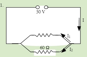
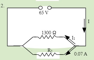
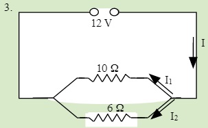
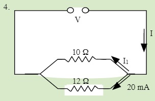
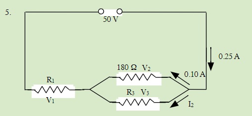
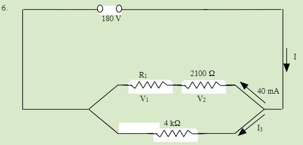
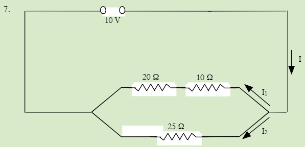
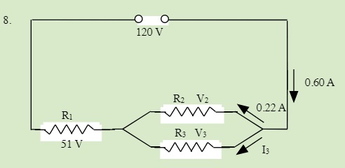
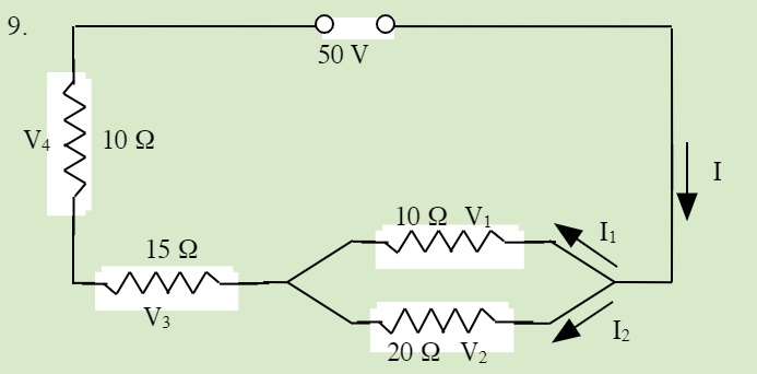
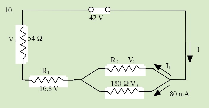
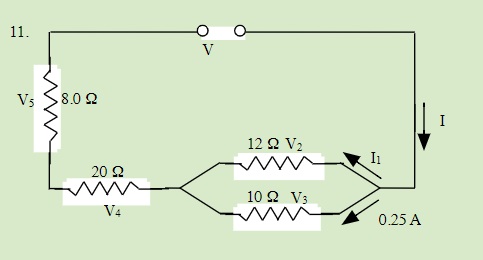
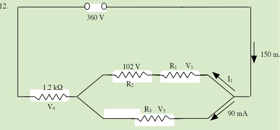
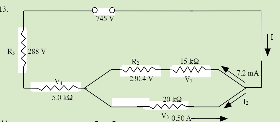
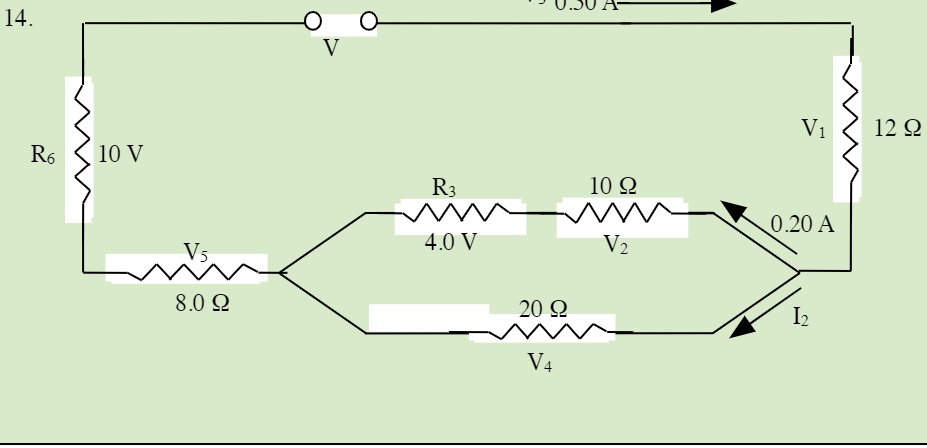
QUESTIONS 23.5 Solving Series and Parallel Resistor Circuits
Solve for all unknowns in the following circuits:
QUESTIONS 23.6.1 Creating Different Resistor Combinations
Using 3 identical resistors, how may circuits can you make with different total resistances? You should be able to create 4 combinations. There are actually more.
Some unusual combinations???
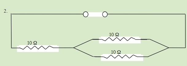
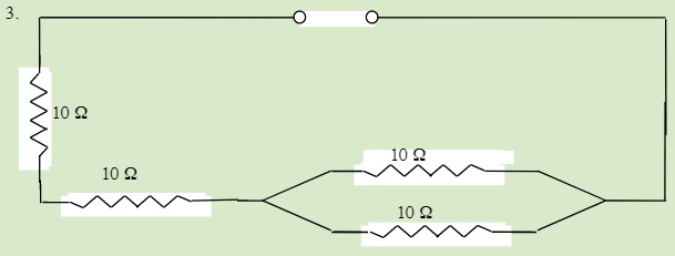
QUESTIONS 23.6.2 A Trick Circuit Combination
Which circuit shown below will have the greatest current flow?
REFERENCES:
